ASSEMBLING, TIME IS SHORT!
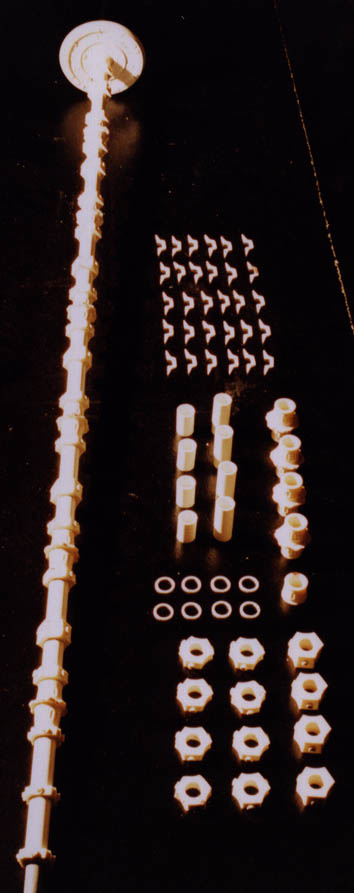
The column supporting all the modules consists of 3 tubes in carbon fibre slided one into the other. Fastenings of the modules are slided and glued on, with plastic tube spacers of the column final diameter. At each end two plumbing t-squares receive the base vertical supports. The weight of the modules slightly bend the column, small brass wedges slided into the t-squares and screws judiciously placed are enough to return its rectilinear shape.
The half-engine blocks are assembled, some open seals are filled with a coachbuilder putty and some details are added to these places. The depth of the reactors rear flanges is not enough significant, due to a problem of casting. They are thus completed by styrene sheets and sanded. The reactors grids would also deserve to be drive in, but the lack of time does not enable me to rebuild the 6 locations! The reactors with screws embedded in the resin are glued on the back plate, nuts secure their fastener. The whole is glued on the block. It remains to add some pipes according to the photographs from the movie.
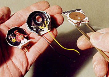
The antenna is assembled by gluing the photoetched stiffeners on the vacuumformed cupolas. A central sight is represented by a tiny photoetched grid glued around a syringe needle. After having put a Humbrol gray primer with a brush (big error!!), painting with a satin white spray goes wrong, there is a reaction with the underlayer and the whole blister! I am obliged to strip with acetone, the cupolas curl but the already glued stiffeners limit the damage, phew! The lack of time and the absence of helping parts do not enable to build a second version of it.


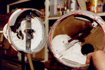
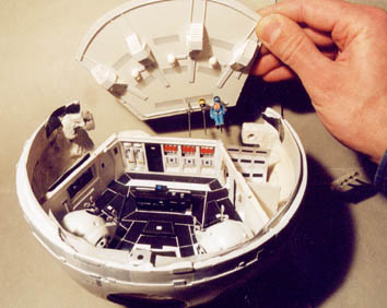
The connection of the half-spheres is correct, but there are still details wrong. The cockpit location is modified for the last time, and the central tape almost rebuilt for the 3rd time!
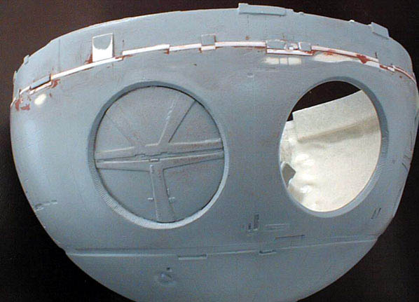
A fast attachment system is set up to be able to connect the sphere to its support cone by a 1/4 turning movement. All this front part is collapsible to reach the electrical system.

A damn helping hand
At the end of February 2001, two weeks before the envisaged end of work, Olivier Herman comes to give me a serious helping hand. He concentrates on the painting of the internal pods, the preparation of the external pod and especially on the construction of the external pod jointed arms. They are assembled starting from brass rods and elements in styrene and cardboard. The internal pods arms are simplified, they are in cardboard and printed paper.

The pod bay
The bay is built with Sintra, with a printing of the groundsheets glued and a ceiling out of diffusing neon cover. It is painted satin white, while masking the neons locations. The low thickness of the coat of paint lets pass the light by all the ceiling surface, with a more significant lighting by neons. The walls are formatted to correspond to the reliefs which can be seen on the photographs, the ventilation grids of the ceiling are out of resin, pipes are out of data-processing sheats. The workbench is out of Sintra and there are some Super Sculpey small accessories.
The pods supports are in Sintra and styrene, some details are out of paper glued with double-sided tape. The exiting pod support is connected to the sphere with HO scale rails, which makes it possible to bring electricity to the 4 high-luminosity white leds which simulate the headlights. In a flash to the model makers of ILM which had stuck a Star Wars poster in the Princess Leia's Blockade Runner cockpit, a 2001 poster is glued behind the David Bowman character into the pod.