
BEGINNING OF THE CONSTRUCTION
August 15, 1998, I begin the construction of the pod, simple element initially, while waiting to obtain the 1/100 Discovery blueprint. The pod dimensions are given in the book of Piers Bizony (6,98 feet in diameter, which gives us a total height of 7,21 feet), and two splendid drawings are a good source of information. So, the 1/100 pod measures a little less than an inch, which makes it less simple to realize than it does appear! The back view, missing on the documents in my possession, is directly photographed on the television screen.
Still a problem of dimension! According to the photographs of the pods bay and the one of Frank Poole going up in a pod following David Bowman, the dimension I have is good. But according to the photographs of the outgoing pod of the command sphere, this dimension is too small! The pod would be supposed to measure 8,85 feet. If I compare to the dimension of 7,21 feet (to keep the proportions), the Discovery would measure only 439 feet!
Finally, I suppose that the 1968 model version had not be well put on scale compared to the lifesize version, some documents give a 9 feet dimension and some other a 7,21 feet. I decide thus to keep my dimension of 7,21 feet. Even if the pod will be a little small compared to the sphere , it will be well proportioned compared to the small astronaut inside...
The original of the pod is realized with a red beech ball, the external cones being out of plastic. Pieces of styrene, stretched plastic and half-pearls complete the base form.
The pod is moulded in silicone, then some tests of casting are carried out. To avoid using resin, I try to run styrene dissolved in trichlore, but the result is not good, the styrene retracting while drying. So, the final version is casted with a polyurethan resin. I use one that does'nt have the disadvantage of the traditional resins, the odor. It is completely odourless (from where the possibility of using it in interior, which also solves the problems of temperature and moisture), is white, very liquid and of fast release from the mould. Its only disadvantage, the pot life (approximately 5 minutes). You should use only small quantities. Its references: resin G20 Sika, reference 50606 in the french shops Rougier et Plé.
In September 1998, I recover the five sheets of the 1/100 blueprints on the occasion of a visit at Jean-Marc Deschamps, as well as a model of Lunar Models not assembled. Disillusion: the plans are wrong! In the scale (1/96 according to my calculations) and in the form. The drawing of Simon Atkinson is much more accurate to the movie model, so it is it which will be used as a basis for construction. I will even though use the 1/96 blueprints for some parts. In fact, the plans correspond to the 2010 Discovery, with all that differences...
NOW THE SHIP
The antennas
After the pod which was only a training, the true construction can be launched. I start with the antennas, small parts annoying to build, but nevertheless essential for the success of the ship shape. The difficulty lies in the many internal and external stiffeners, all in relief! I try to engrave streaks in Playpat, air drying modelling clay, to cast the part in plasticine, to mould it in silicone then to recast it with styrene. But the result is really not terrible, the large antenna is too much curved and the streaks are not enough deep. Result, I use the AMT Millenium Falcon antenna by engraving streaks. Several tests of casting are carried out directly on this part, with quite as bad results. I even try to use magic plastic, a thermoplastic material, but it is not adapted for sanding.
Finally, I start again at zero by making the original antennas into positive. I glue small pieces of stretched plastic on the Millenium Falcon antenna for the large antenna, and on a Slave 1 antenna for the small one. The straight stiffeners are glued before engraving the shape of the circular stiffener then to glue it with stretched plastic.
The command sphere
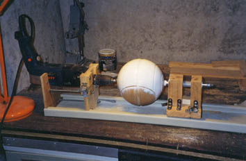
A possibility would have been to use a 7,87 inch diameter PMMA or Plexiglass ball. But this dimension does not correspond completely to that desired, and not finding an appropriate sphere I must resolved to make it turn with a lathe in ash by a cabinet-maker craftsman, throats included. This made, I putty some flaws with wood paste, I sand all of it then spray a coat of white paint. And cracks appear everywhere! Thermal shock, bad reaction to painting? I putty the cracks with model putty, I sand the whole on a homemade lathe then I apply a coat of special wood paint.
January 1999, problem of dimension for the throats. Those which I have given to the craftsman were to be false, the proportions do not seem good. I recut them with the chisels and I decrease the depth of the central throat by gluing a plastic tape. The remainder of work is simple, it's just cutting and gluing of small plates. The only problem relates to the location, the photographs being contradictory (surely because of the 2 models on different scales built for the movie) and there is no document on the left side, except a very short shot in the movie and a very small photograph found on Internet. In conclusion, I work with the photographs drawn from the movie for the right side and on the movie itself for the left side.
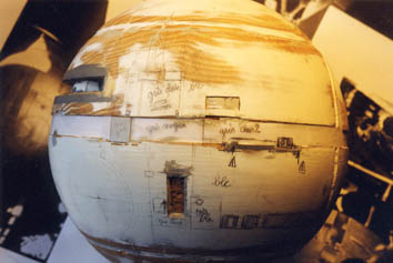
Other problem, the cockpit. The documents are not clear on the exact form, I realize a plunging front according to a photograph of the " small " model of 15 feet built for the movie, the remainder being cut according various photographs.
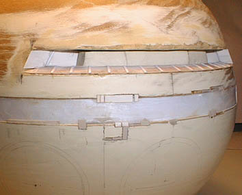
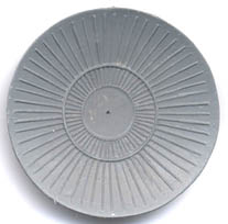
No particular problems for the raised plates and cuttings at various places of the sphere. I add a lot of small recesses, especially towards the bay doors, according to the images of the movie. The streaks surrounding the airlock door are more problematic to realize. I try to engrave them directly on wood, the result is bad. I then roll a toothpaste cap in Plastibo, the result is random. Finally, I glue small pieces of stretched plastic, I sand them to obtain the desired angle, then I regrave the streaks. The door itself is made out of very fine aluminum, the control panel is in styrene and paper.
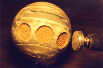
The sites of the 3 bay doors also pose problems at the time of cutting them. A stretchable wood bit deviates according to the consistency of wood, I must make numerous small holes and remove what remains with chisel, what givse some bad circles. I enlarge the holes to the external diameter to fit tubes chamfered with the lathe and streaked with a heated head screw.
|
|
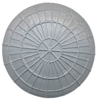
The bay doors are build with pieces of trashcan cover. Their engraving, different according to the doors, is done without difficulties.