The antennas (twice)
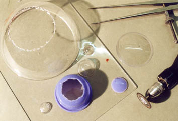
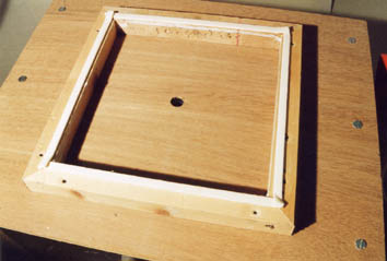
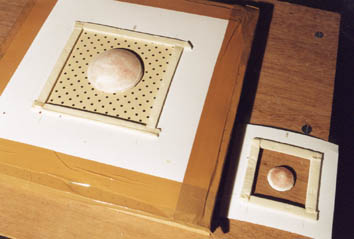
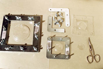
A piece of display stand and a cap are cut out to obtain 2 parts of the antennas size and contour, they are glued on supports to raise them, plasticine is used to produce a slight cone under these supports. This shape will make it possible to more easily release the vacuumformed parts. The whole is moulded out of silicone, then a polyester gel-coat (it is what I had under the hand at this time) is done. These 2 casts will be used as masters for the vacuumforming operation. In fact, I realize that the plastic parts can be used directly as masters, they support heat very well (still a missed occasion to save resin!).
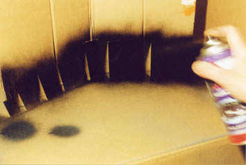
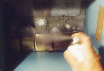
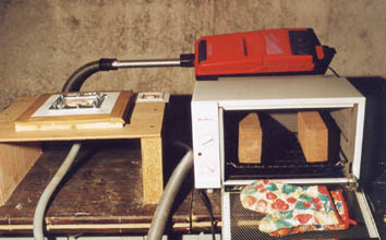
The principle of vacuumforming is very simple : a heated plastic sheet is flattened on the master by aspiration. I build a vacuumforming table whith the help of articles found on Internet and in the Fine Scale Modeler magazine of March 1998: a wood chest on which is fixed a metal sheet with plenty of small holes and a homemade connector to fix the pipe of an old vacuum cleaner. All is built with materials from the spare box, cost of the opération : 0 F, just a little time!
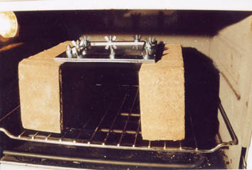
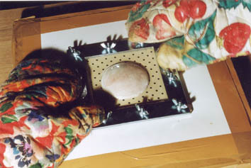
For the plastic I use cellulose acetate like the one which covers files. In spite of its 2/10 mm thickness, it is held sufficiently well by itself. A mini oven heats to 250 °C the sheet fixed within a homemade metal angles frame, as soon as the sheet is quite sagging (approximately 30 seconds if the oven is quite hot) you remove the whole quickly to flatten on the master, without forgetting to start the vacuum cleaner. After 10 seconds, the part is ready, you just have to cut it!
Some badly air bubbles decide me to sand the antennas, they are still sufficiently translucent to be able to align the interior and external stiffeners during gluing.
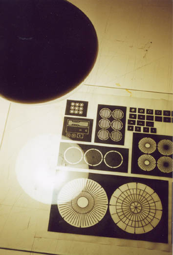
The photoetching process is identical to that used by the electronics specialists to carry out the printed circuits. The first stage is to print the darkest possible image on a transparent support. The lines of this image must be the smoothest possible, the minimum is a 600 dpi laser printing. Some products available in electronics stores reinforce the contrast of the printing so that the black is deeper.

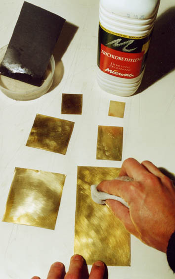
The " typon " thus obtained is put on a 0,2 mm thickness brass sheet. A face of this one is sanded with a 1200 wet sandpaper to remove its impurities, then cleaned with trichlore to degrease it and eliminate the finger marks. Its other face is protected with spray paint so that the sheet is etched only by one side. The cleaned face is sensitized thanks to a photosensitive varnish. The secret of the success is here: to obtain a uniform layer on all the surface, which appears simple by saying it, but that is much less in practice. I admit not to have succeeded in obtaining one perfect layer, even after very many tests.
 |
|
Well protect the sheet from daylight before revealing it photographically. A square of glass strongly plates the printed face of the typon on the sensitized face of the brass, slightest curl can cause deformations in the photographic print. A UV lamp placed at approximately 15 cm of the whole makes it possible to insolate brass. Optimum time depends on varnish used, layer thickness, power of the lamp... Just for information, a time of one one minute ten seconds allows me to obtain the best result. If " holes " in the developed print appear, you can correct them as far as possible with a permanent felt-tip pen like the one which write on transparencies. The insolated sheet is plunged in a bath of 20° C minimum developer, the image of the typon appears progressively, the main thing is to remove the sheet at the time when contrast is most significant. Time is more or less long according to the temperature of the developer bath. Putting the developer can on a radiator three hours before using it, I manage to develop a sheet in 25 seconds! When the sheet is withdrawn, the developing process is stopped while passing it under running water.
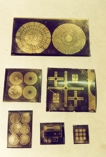
At last, let soak the sheet in a perchloride bath, the exposed brass is etched by this solution whereas the protected parts are not. The operation is long, several hours to go through the 0,2 mm, it can be accelerated with heating of the bath temperature. It is enough to put hot water in a bowl where the perchloride bowl is put, by renewing it every half-hour to maintain the temperature. The sheet jamed in a PVC tube split in his length direction is plunged in the bath head in bottom, this position avoids clogging. When brass is completely transpierced, remove the sheet, rinse it and clean it with acetone to remove the varnish traces and back painting. According to the bath clogging state (sheets back painting clogs it very quickly) and the temperature, the operation varies between two hours and half and four hours!
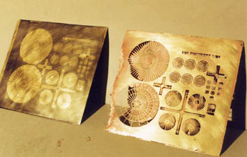 | 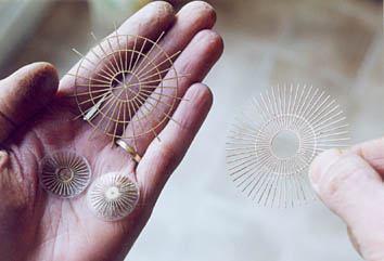 |
A developed sheet and the same with a missed etching | The final stiffeners |